G Clamp

In an effort to catch up to myself and sync this blog with what I’m actually doing, the next few posts will be short, bit informative, hopefully.

After finishing the drill drift, we were given the plan for the G Clamp. This piece formed a part of our first assessment, so it was fairly important.

We were using 12mm thick steel and the clamp itself is roughly 60mm squarish, so its a fairly solid piece of metal. Done right, this could be a nice object.

In addition, there were some new techniques, large radii and tight tolerances.

image

All in all, I think it went fairly well!. An awful lot of filing there…

Job 3 – Profile plate.

I only have one piece to show off this week, which sadly doesn’t look like much of anything, but in fact was a fairly tough exercise in patience and precision.

A perspective of the profile plate, showing the edges and faces.

A perspective view of the profile plate

The piece is called a profile plate and is very simply, a nearly square piece of 6mm thick mild steel, with various profiles cut out of it, making it look like three stair steps. Each of the stair steps is a different height and crucially,. each of the stair steps is of a different width. The tolerances for the heights was 0.25 of a millimeter and the tolerances for the width was 0.1 of a millimeter. Each face on the piece had to be flat and square.

The back 'side' of the profile plate.

Profile Plate – rear view

In addition, the piece had three holes drilled into it, two small 3mm reamed holes at each ‘corner’ of the steps and a single M6 tapped hole at a squarely positioned 10mm up and right of the bottom left edge. All measurements come from a datum point which is the left edge of the piece.

What went wrong?

It’s an old adage that a bad workman blames his tools, but I’ll explain what happened and allow you to draw your own conclusions.

In the hand fitting section, there is a single Vernier height gauge between all of the people in the section. The gauge is a lovely thing, but it is old. Just recently, when the gauge is zeroed, another look at it would occasionally show the tip of the measurement point about a millimeter above the marking out table. Only occasionally, but it was happening. I suspect that was what happened to me when I started to measure out the 3mm reamed holes, which explains why the 3mm reamed holes look as if they are off position.

However, there is another old saying which states ‘measure twice, cut once’. There are vernier calipers aplenty in the section and I could quite easily have used them to double check the measurements – and should have, especially considering I had my suspicions about the height gauge prior to this job.

As a matter of interest, the height gauge has now been given a makeshift repair so we can use them while awaiting a new gauge to be delivered.

So, while I could blame the tools, I don’t. I should have double checked the measurement, but didn’t. My fault. It’s a good lesson.

Also, I must have had some sort of twitch while stamping my name on it. The final E wandered a bit.

The front side of the profile plate, showing where I made a mistake with the stamping.

The front of the profile plate.

In reality, I’m really pleased with this piece. I managed to get exactly on measurement or well within tolerances on all dimensions (except the 3mm holes) and learned a few very good lessons. In particular, I’ve found there is a certain zen like calm to be found in filing, which I’ll expand upon more when I’ve finished my next piece, which is a G clamp.

Till then.


Job 2 – Drill Drift

After the first job was finished and I’d stopped grinning like a fool, I started in on the second job, which promised to have some actual real life applications.

The drills we use in the training workshop are great big pillar drills, which stand upright, taller than me (I’m six feet tall) and are operated by pulling a handle towards you, which lowers the drill chuck and hopefully the bit, towards whatever you are drilling holes in. The drill chuck itself is at one end of a tapered metal rod, which fits into a metal sleeve which doesn’t have a taper. Essentially, when you fit the chuck, you slide the rod into the sleeve and give it a good push. The taper on the rod is essentially the only thing holding the chuck onto the drill.

The drill drift is intended to help get the chuck out, by sliding into a socket aligned with the top of the tapered rod inside the sleeve. A healthy tap on the big end of the drill drift and the chuck falls into your hopefully prepared hand. That’s the theory anyway. It’s a tool. My first tool.

The plan we were given instructed us to hacksaw off a 160mm long section of 5 x 25mm mild steel from the material stock. Once we had that, we were to make each end flat and square, choose one end of the piece to act as our datum point, then follow the job plan to produce the tool.

It’s an odd thought, but before starting this, I would never have thought of a hacksaw as being a shortcut tool, but it really is. Especially when you are looking into the abyss of hand filing a fairly significant chunk of metal away, remembering that at the end, we have a tolerance of +/- 2.5 microns. Hacksaws seem a bit cheaty, really, but I’m glad we have them.

The end result had to be 151mm long, 22mm high and 5mm thick. One end was to be tapered to 2 3mm radii (giving us a half circle), the other to 2 12.5mm radii (again, a half circle). The big end has a 6mm hole drilled into the center point of the radius, and the hole is to be countersunk 3mm.

All edges, including the radii, had to have a 1.5mm chamfer applied. Again, this is all hand tools, the only machine used is the drill.

My first tool.

My second job, a drill drift.

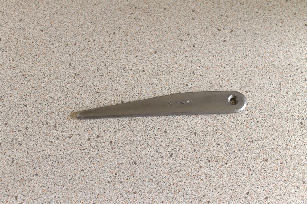
Job No. 2 – Drill Drift

I must have done something right, this tool didn't mind standing like this at all.

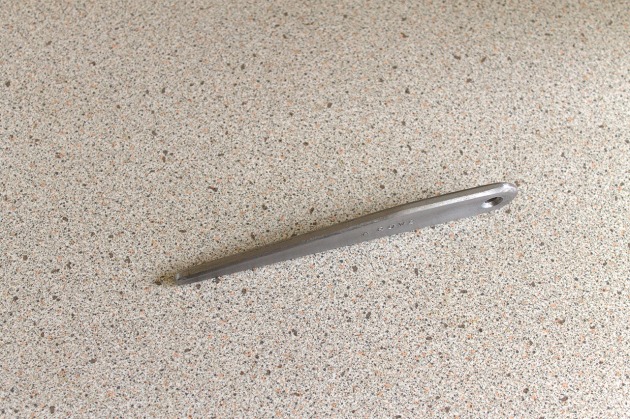
Drill Drift standing on edge

The second job I completed as an apprentice, a drill drift.

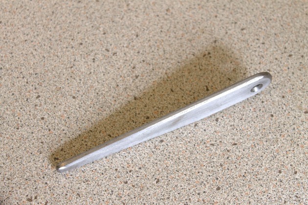
Drill drift standing on edge, showing my chamfers.

I'm lucky to have got away with this countersink, I have a feeling the only reason it snuck past is because it was just my second job.

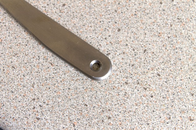
Job No. 2 botched countersink.

If you look carefully, you can see I buggered the countersink up. Also, I am about a millimeter out of center with the hole. Not much, but it’s interesting how obvious it is to the eye. There’s a lesson in that.

Fairly proud of how flat and square the edges are, as well as my chamfers. I still need a lot of practice, but hey, that’s the point of being an apprentice isn’t it? Chamfers on rounded ends are hard!

First Training Job

This is my first post on the blog, so it hasn’t really found it’s personality yet. I’ll just pile in and see how things turn out.

I started my first day as an apprentice toolmaker at the Rolls Royce North East Training Center, near Newcastle Upon Tyne, on the 14th July 2014. The training center is on the banks of the river Tyne, and is an adjunct to the Michell Bearings factory, which primarily makes gigantic bearings for the marine industry.

The first day was primarily based around Health and Safety briefings and paperwork, understandably enough, though towards the end of the day, we were told what our first job would be.

Nothing spectacular, it’s a small metal thing, measuring 16mm high, 16mm thick and 40mm long. It has three holes in it, a 12mm deep blind hole tapped to M10, a through hole tapped to M10 and a 10mm deep blind hole countersunk to 3mm. Each end has different techniques applied to it, one end with a 1mm chamfer all around the edge, the other with a 1mm radius all around the edge.

To start with, we were told to hacksaw a piece of material off a stock bar, then get to work with a hand file. On this job, all the edges have to fit a tolerance of 2.5 microns, or 1/4 of a millimeter.

Took a couple of days, but I was really pleased with the result. My first bit of work.

The first job completed as an apprentice toolmaker.

First Job

The chamfers on one end of job no. 1

Job No. 1, chamfers

A picture showing the small radius applied to the end of a small obling piece of metal.

Job No. 1 radius